
Introduction
An Incremental Rotary Encoder is a type of position sensor that provides information about the change in position, speed, and direction of rotation of a shaft.
Unlike absolute encoders, it does not provide a fixed digital value for each position but instead generates pulses as the shaft rotates. These pulses are counted to measure movement. They’re often used in applications where highly precise measurement and motion control is required, such as robotics.
Working Principle
Incremental rotary encoders generate A/B digital output signals based on a specific number of pulses per rotation (PPR). In this way, the angular motion of a shaft is converted into a code (encoded) to determine its velocity or relative position.
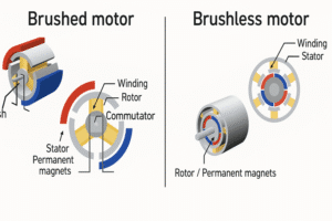
Components of an Incremental Rotary Encoder
The components include :
- Shaft or Disc
- Light source/Magnetic Element/capacitive plate
- Sensor or Detector
- Electronics/Signal processing circuitry
- Output Channel (A, B, C and Z
- Housing/Enclosure

How Does an Incremental Rotary Encoder Work?
Incremental rotary encoders are honestly everywhere—any machine with a spinning shaft probably has one hiding inside. They’re basically the eyes and ears for tracking how far, how fast, and which way something’s turning. You’ve got the basics: a shaft, a code disc slapped onto it, some kind of signal source (could be light, could be magnetic—depends on the flavor), and a detector waiting to pick up the action. As the shaft turns, the code disc tags along, and every little change gets picked up by the detector, which spits out a bunch of pulses.
Usually, you’ll hear about channels A and B—those are just two separate lines of pulses that help you figure out not just how much something’s turning, but also which direction it’s spinning. Count the pulses, boom—you get speed, direction, distance, the whole deal. The diagram up there (yeah, the one you’re probably squinting at) lays out all the main bits. Simple in theory, but super handy in real life.

To determine direction, incremental encoders use two output channels, labelled A and B, that are offset by 90 degrees (quadrature). When the shaft rotates, the phase relationship between these signals indicates whether the movement is clockwise or counterclockwise.

Some encoders also include a Z-channel, which generates a single pulse per revolution, serving as a reference or index point. By counting the pulses from channel, A and B and observing their phase difference, the control system can calculate both speed and direction of rotation. However, because the encoder only provides relative position, it requires a reference point each time it starts up. If power is lost, the encoder cannot retain its position information and must be re-positioned to the initial place to establish a baseline.
Working
As the shaft rotates, the pattern on the disc modulates the chosen sensing field whether optical, magnetic, or capacitive which the sensor translates into two phase-shifted signals. The signal processing electronics condition and align these into A/B quadrature waveforms; motion controllers then count edges to determine rotational velocity and position, with the Z index pulse marking an absolute reference point for homing or calibration.
This integration of mechanical, optical, magnetic, or capacitive components, together with sophisticated signal conditioning, enables modern encoders to offer precise, robust feedback essential to today’s motion-control applications.
Types of Incremental Encoders
1. Optical Incremental Encoder
2. Magnetic Incremental Encoder
3. Capacitive Incremental Encoder
4. Mechanincal Incremental Encoder
Real-World Applications of Incremental Rotary Encoders
- Industrial Automation: Used in conveyor belts, packaging machines, and assembly lines to control movement and position.
- Robotics: Help robots track motor rotations for precise movement and positioning.
- CNC Machines and Manufacturing: Provide feedback for cutting, drilling, and milling machines to ensure high accuracy.
- Elevators and Lifts: Track shaft rotation to monitor speed and floor positioning.
- Renewable Energy: Measure the rotation of wind turbine blades and generator shafts.
- Automotive Systems: Found in electric power steering, throttle control, and wheel speed monitoring.
- Aerospace and Defence: Used in actuators, navigation systems, and aircraft control surfaces.
- Medical Equipment: Present in diagnostic machines, robotic surgery tools, and infusion pumps for precise control.
- Printing and Scanning Devices: Ensure accurate movement of rollers and print heads.