
Introduction
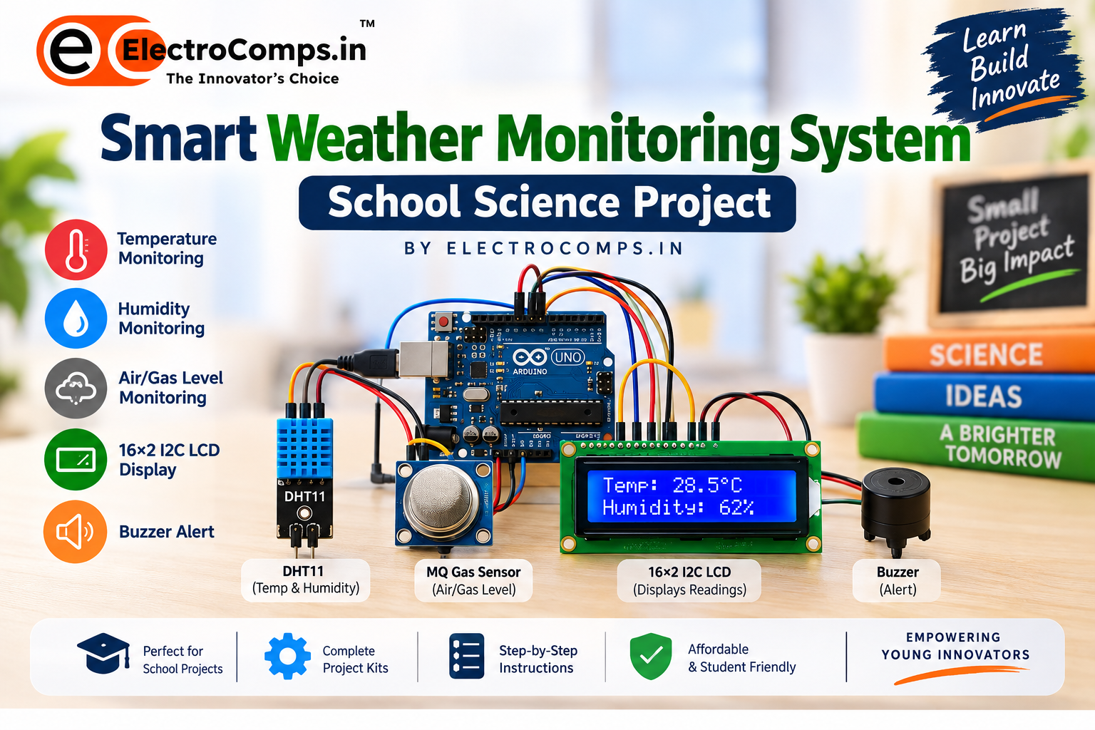
The Smart Weather Monitoring System is an Arduino-based school science project that monitors temperature, humidity, and air/gas levels. The readings are displayed on a 16×2 I2C LCD, while a buzzer provides an alert when programmed limits are exceeded.
This project is suitable for school science exhibitions, STEM activities, robotics projects, and INSPIRE-MANAK preparation.
Explore More Projects from ElectroComps.in
- Battery for arduino projects rechargeable
- AI Assistant Project
- Wireless Power Transmitter Tesla Concept
- Smart Irrigation Science project Kit
- Rain Detection and Alarm Science Project Kit
- Fire Detection and Alarm Science Project Kit
- Automatic Smoke Detection and Alarm Science Project Kit
- Automatic Gas Leakage and Alarm Science Project Kit
- Automatic Fire Detection and Extinguisher Science Kit
Components Required
- Arduino UNO x 1
- DHT11 Temperature & Humidity Sensor x1
- MQ Gas Sensor x 1
- 16×2 I2C LCD x 1
- Buzzer x 1
- Breadboard x 1
- USB Cable x 1
How Does It Work?
The DHT11 measures temperature and humidity, while the MQ Gas Sensor provides an analog air/gas reading.The Arduino UNO processes the sensor readings and displays them on the LCD. When a programmed threshold is crossed, the buzzer activates.
Sense → Process → Display → Alert
Circuit Diagram
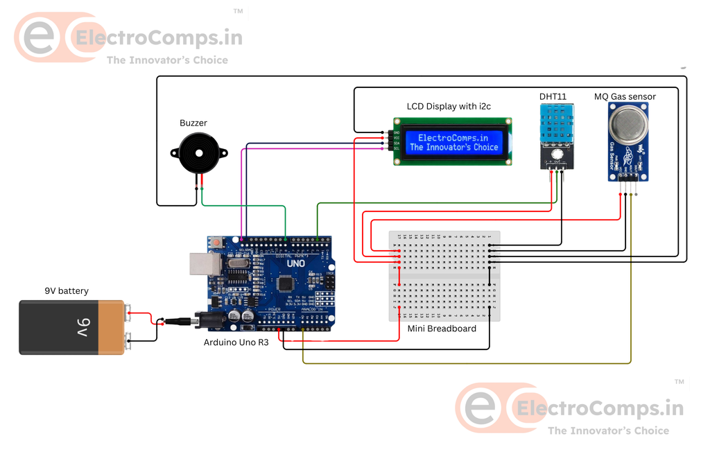
The circuit connects the DHT11, MQ Gas Sensor, I2C LCD and buzzer to the Arduino UNO.
Buzzer connectionss with Arduino
| Buzzer | Arduino UNO |
| + | D8 |
| − | GND |
MQ Gas Sensor Connections with Arduino
| MQ Sensor | Arduino UNO |
| VCC | 5V |
| GND | GND |
| AO | A0 |
DHT 11 Sensor Connections with Arduino
| DHT11 | Arduino UNO |
| VCC | 5V |
| GND | GND |
| DATA | D2 |
LED Display Connections with Arduino
| LCD | Arduino UNO |
| VCC | 5V |
| GND | GND |
| SDA | SDA |
| SCL | SCL |
How the Project Works
The DHT11 sends temperature and humidity data to the Arduino. The MQ sensor provides an analog reading through A0.
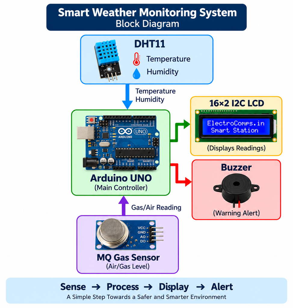
Arduino processes these values and displays them on the LCD.
When a reading crosses the programmed threshold, the LCD displays an alert and the buzzer sounds.
Arduino Code
Install these libraries:
- DHT sensor library by Adafruit
- Adafruit Unified Sensor
- LiquidCrystal I2C
Then upload the Arduino program to your UNO.
#include <Wire.h>
#include <LiquidCrystal_I2C.h>
#include <DHT.h>

#define DHT_PIN 2
#define DHT_TYPE DHT11
#define BUZZER_PIN 8
#define MQ_PIN A0

LiquidCrystal_I2C lcd(0x27, 16, 2);
DHT dht(DHT_PIN, DHT_TYPE);

#define HIGH_TEMP 35.0
#define HIGH_HUMIDITY 80.0
#define GAS_THRESHOLD 400

void setup() {

  Serial.begin(9600);

  dht.begin();

  pinMode(BUZZER_PIN, OUTPUT);
  digitalWrite(BUZZER_PIN, LOW);

  lcd.init();
  lcd.backlight();

  lcd.clear();
  lcd.setCursor(0, 0);
  lcd.print("ElectroComps.in");
  lcd.setCursor(0, 1);
  lcd.print("Smart Weather");
  delay(2500);

  lcd.clear();
  lcd.setCursor(0, 0);
  lcd.print("Initializing...");
  lcd.setCursor(0, 1);
  lcd.print("MQ Sensor");
  delay(3000);

  lcd.clear();
}

void loop() {

  float humidity = dht.readHumidity();
  float temperature = dht.readTemperature();
  int gasValue = analogRead(MQ_PIN);

  if (isnan(humidity) || isnan(temperature)) {

    lcd.clear();
    lcd.setCursor(0, 0);
    lcd.print("DHT11 ERROR!");
    lcd.setCursor(0, 1);
    lcd.print("Check Sensor");

    delay(2000);
    return;
  }

  lcd.clear();
  lcd.setCursor(0, 0);
  lcd.print("Temp: ");
  lcd.print(temperature, 1);
  lcd.print((char)223);
  lcd.print("C");

  lcd.setCursor(0, 1);
  lcd.print("Humidity: ");
  lcd.print(humidity, 0);
  lcd.print("%");

  delay(2500);

  lcd.clear();
  lcd.setCursor(0, 0);
  lcd.print("Gas Level:");

  lcd.setCursor(0, 1);
  lcd.print(gasValue);

  if (gasValue >= GAS_THRESHOLD)
    lcd.print(" HIGH");
  else
    lcd.print(" NORMAL");

  delay(2500);

  bool highTemperature = temperature >= HIGH_TEMP;
  bool highHumidity = humidity >= HIGH_HUMIDITY;
  bool highGas = gasValue >= GAS_THRESHOLD;

  if (highGas) {

    lcd.clear();
    lcd.setCursor(0, 0);
    lcd.print("GAS DETECTED!");
    lcd.setCursor(0, 1);
    lcd.print("Check Air!");

    alarm();
  }

  else if (highTemperature && highHumidity) {

    lcd.clear();
    lcd.setCursor(0, 0);
    lcd.print("TEMP & HUMID");
    lcd.setCursor(0, 1);
    lcd.print("HIGH ALERT!");

    alarm();
  }

  else if (highTemperature) {

    lcd.clear();
    lcd.setCursor(0, 0);
    lcd.print("Temperature");
    lcd.setCursor(0, 1);
    lcd.print("HIGH ALERT!");

    alarm();
  }

  else if (highHumidity) {

    lcd.clear();
    lcd.setCursor(0, 0);
    lcd.print("Humidity");
    lcd.setCursor(0, 1);
    lcd.print("HIGH ALERT!");

    alarm();
  }

  else {

    lcd.clear();
    lcd.setCursor(0, 0);
    lcd.print("Weather:");
    lcd.setCursor(0, 1);
    lcd.print("NORMAL");

    delay(2000);
  }
}

void alarm() {

  for (int i = 0; i < 3; i++) {

    digitalWrite(BUZZER_PIN, HIGH);
    delay(300);

    digitalWrite(BUZZER_PIN, LOW);
    delay(200);
  }

  delay(1000);
}
Alert Conditions
The example program uses:
#define HIGH_TEMP 35.0
#define HIGH_HUMIDITY 80.0
#define GAS_THRESHOLD 400
The system can generate alerts for:
- Temperature ≥ 35°C
- Humidity ≥ 80%
- MQ sensor value ≥ 400
- High temperature and humidity together
These are demonstration thresholds and can be adjusted according to testing conditions.
Important: MQ sensor values are relative analog readings and should not be treated as accurate gas concentration in ppm without proper calibration.
How to Test the Project
1. Test Temperature
Place your hand near the DHT11 and observe the temperature reading.
2. Test Humidity
Gently breathe near the DHT11 without touching it. The humidity reading should temporarily increase.
3. Test MQ Sensor
Allow the MQ sensor to warm up and observe its reading through the Serial Monitor.
4. Test Buzzer
Temporarily reduce a threshold such as:
#define HIGH_TEMP 25.0After testing, restore the required value.
Common Problems
LCD Not Displaying?
Check the I2C address. The code uses:
LiquidCrystal_I2C lcd(0x27, 16, 2);Some LCD modules use 0x3F instead. Also check SDA, SCL, power and contrast.
DHT11 Error?
Check:
VCC  → 5V
GND  → GND
DATA → D2
MQ Sensor Reading Unstable?
Allow sufficient warm-up time. MQ readings can change depending on sensor condition, environment and calibration.
Buzzer Not Working?
Check:
Buzzer + → D8
Buzzer - → GND
🎓 What Students Learn
This project provides practical experience with:
- Arduino programming
- Temperature and humidity sensors
- Analog sensors
- I2C communication
- LCD displays
- Threshold-based programming
- Automatic alerts
- Environmental monitoring
Students learn the complete process:
Sensor → Arduino → Data → Display → Alert
🏫 Perfect for School Science Projects
This project can be used for:
- School science exhibitions
- Science fairs
- STEM activities
- Robotics projects
- INSPIRE-MANAK preparation
- Classroom demonstrations
Students can also explain the project using the simple concept:
“Our system senses environmental conditions, processes the readings using Arduino, displays the information on an LCD, and activates an alert when a programmed limit is exceeded.”
🚀 Future Upgrades
The project can be upgraded with:
- ESP32/ESP8266 Wi-Fi
- Mobile monitoring
- Cloud dashboard
- Data logging
- Real-time graphs
- Automatic fan control
- Solar power
🛒 Build Your Own Smart Weather Monitoring Project
Want to build this project without searching for every component separately?
ElectroComps.in provides DIY educational project kits for students, including science, electronics, Arduino, robotics and STEM projects.
Our project kits are designed to help students build, learn and understand practical working models.
Why Choose a Complete Project Kit?
✅ Project-specific components
✅ Step-by-step project guidance
✅ Hands-on learning
✅ Suitable for school projects and exhibitions
✅ Easy to build and demonstrate
✅ Student-friendly project solutions
👉 Explore the Smart Weather Monitoring System and other DIY project kits at ElectroComps.in.
ElectroComps.in — The Innovator’s Choice
Learn • Build • Innovate